
Introduction
In this article we will focus on the practical use of the BoxID/Clocker reader. The article is intended for those who are already familiar with integrating the reader with a Mitsubishi PLC, if you haven’t already done so, please refer to the first part of the article:
The PLC project from this article in GX Works2 is available for download on our github:
https://github.com/Inveo-spzoo/BoxID-Clocker—Mitsubishi-GxWorks2—Sample-Poroject
List of variables
After configuring both devices, it is time to create the first application using the full power of the reader’s capabilities. Remember that the number of blocks depends on the model of the reader.
However, before we move on to programming, we need to familiarize ourselves with the individual data blocks and their functionalities. One of the basic blocks for operating BoxID/Clocker readers is the “control” block – it allows you to control outputs, read inputs, generate beeps and view login data. Variables with the prefix “Q” are the PLC’s output data, and variables with the prefix “I” its input data.

Opis funkcji poszczególnych zmiennych:
Q_resetNewIdFlag – ta flaga służy do potwierdzenia odbicia nowej karty użytkownika, ustawienie stanu wysokiego jest wymagane aby nastąpił reset flagi I_newIdFlag
I_newIdFlag – ta flaga przyjmuje stan wysoki po odbiciu nowej karty, flaga zostanie zresetowana poprzez ustawienie stanu wysokiego na Q_resetNewIdFlag
I_in1 – stan wejścia 1
I_in2 – stan wejścia 2
I_out1 – stan wyjścia 1
I_out2 – stan wyjścia 2
I_liveBit – bit sygnalizujący poprawną konfigurację obydwu urządzeń
I_uidLen – długość userID
I_uid – tablica danych userID
I_userId – zmienna informująca o tym czy użytkownik jest zarejestrowany w bazie jeżeli ID karty jest rozpoznane to wyświetli się id użytkownika w przeciwnym wypadku pojawi się wartość 64535.
I_group – grupa użytkownika
I_name1 – pierwszy człon nazwy użytkownika
I_name2 – drugi człon nazwy użytkownika
Q_out1_ctrl – wyjście przekaźnikowe 1 (sterowanie cewką)
Q_out2_ctrl – wyjście przekaźnikowe 2 (sterowanie cewką)
Q_soundAccept– sygnał dźwiękowy “accept”
Q_soundReject – sygnał dźwiękowy “reject”
To write data from the PLC to the reader, the handshake must be completed. This is a request for a new user.
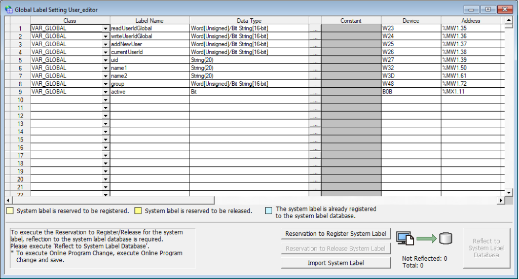
The next basic block is “User_editor”, which is used to both read users and write them to the reader’s memory. Each user has their own group and ID.
There are two ways to add users. We can add them from the built-in web server of the reader or from the PLC level by performing appropriate operations on the data block.
Note! The variables of the “user_editor” block are used for both reading and writing, there is no division into input and output parameters here.
Description of the functions of individual variables:
readUserid – the number of the user whose data we want to read
writeUserId – the number of the user whose data we want to save
addNewUser – we have to set the value to 1 every time before adding a new user, this will set the index in the nearest free space – the value will be automatically set to 0 by the reader so it does not need to be deleted
currentUserId – the index of the user ID we want to save or read
uid – the ID number of the user’s card
name1 – the first part of the user name
name2 – the second part of the user name
group – the group/access level of a given user
active – a bit that allows deactivating the access of a given user without deleting it from memory
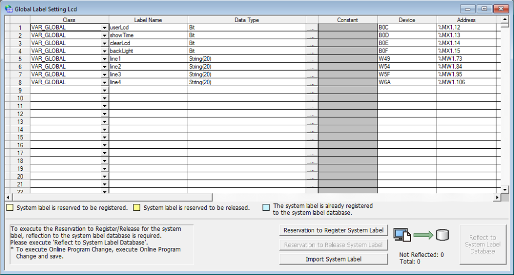
The next important block is “lcd”. The block allows for full control over the built-in display, we have 4 lines of 20 characters at our disposal. This allows us to create a simple menu and display the login result.

Description of the functions of individual variables:
useLcd – setting the high state allows you to take control of the display, low state will display the reader’s IP address
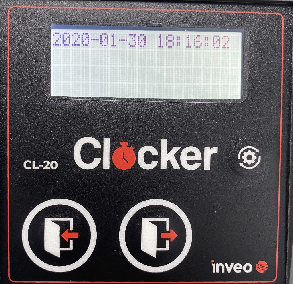
showTime – setting the high state will display the current date and time in the first line
clearLcd – clear the display
backlight – display backlight ON/OFF
line1 – first line
line2 – second line
line3 – third line
line4 – fourth line
The last block is the keypad, we only use it in readers with a keyboard.
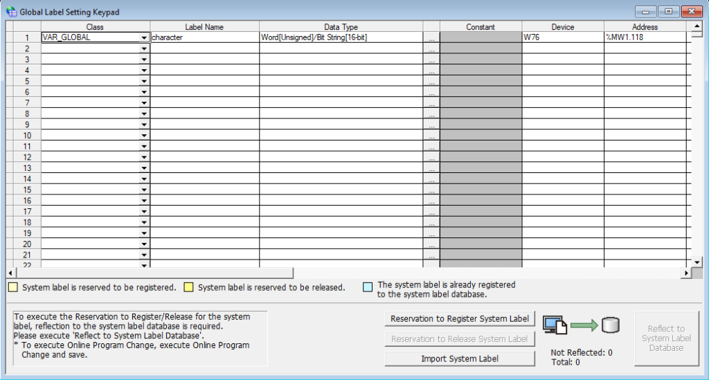
character – character pressed on the keyboard
After familiarizing yourself with data blocks and their content, it’s time to create the first practical application. This will be a simple user management system. In fact, the BoxID reader has a built-in user management system – our task will be to operate it using a few simple instructions.
Access control
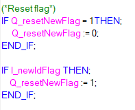
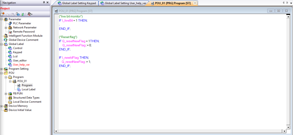
As I mentioned at the beginning, the so-called handshake, i.e. resetting the newID flag, is required for the reader to work correctly:
We can start by manually leading two users to the system, then we will move on to creating a simple program that will trigger the built-in relay output of the reader for 3 seconds in the event of correct authorization.

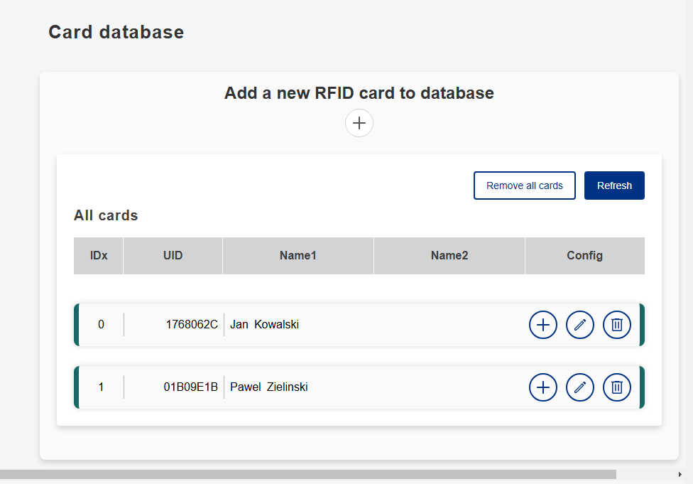
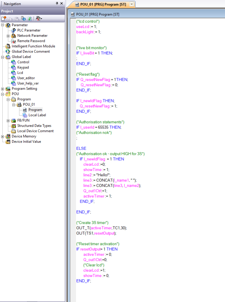
As you can see, I’ve added two users. After bringing the card close to the reader and pressing “Get last read UID” the last read code will be entered into the Card UID field. Below is the implementation of a simple access control program in ST language:
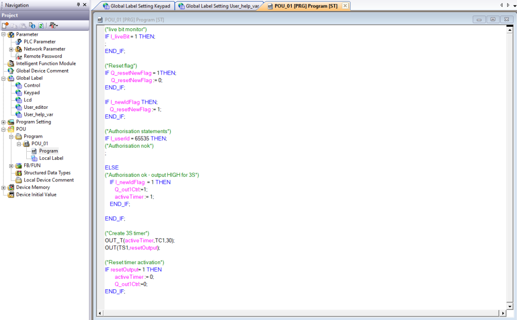
Program operation:
If the identifier is incorrect, the user is not logged in. In case of positive verification, the system activates the relay output for 3 seconds.
After the specified time has elapsed, the output is automatically reset and the system returns to the state of waiting for the next user.
Correct login:
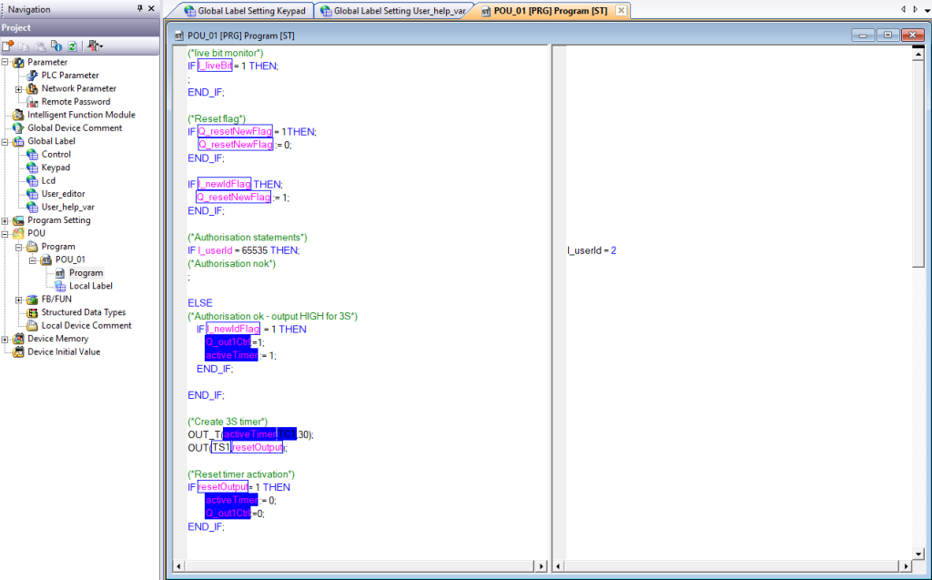
Incorrect login:
In case of a successful login, the value of I_userId takes the value of the user index, otherwise it takes the value of 65535.
User management
Before we move on to user management, we will create a block of auxiliary variables User_help_var:

We already know how to verify users, the next step is to learn how to read existing users from the built-in reader database.
Currently, our user database looks like this:

So let’s try to read the user with index 1:
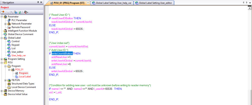

The above code allows both reading and writing users. It has been prepared in such a way that by entering values into auxiliary variables with postfixes “Button” and “Set” you can manage the database, e.g. from the HMI level. To read a user with index 1, set the “currentUserId” variable to 1 and set the “readUserIDButton” auxiliary variable to 1. As you can see in the preview above, the data of the user with index 1 has appeared.
We have already mastered reading a user, the next and final step is to master writing new users from the PLC level. As in the case of manually adding a user, you need to enter the name and surname and bring the new card close to the reader.

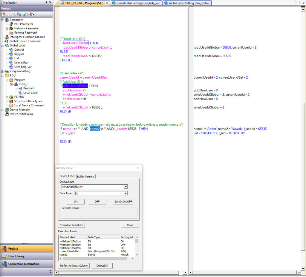
After entering this data, all you need to do is bring the card you want to assign to this user close to the reader and then set the “writeUserIDButton” variable to high.

The user will be entered into the nearest free index in memory. This is how we cleverly entered Adam Nowak into the user database.
LCD display
By default, the display should show the IP address

Below we see the contents of the “lcd” block:
Setting the “useLcd” variable to “true” allows you to take full control of the display.

The “showTime” variable allows you to display the current time on the first line, and “backlight” allows you to backlight the display.
Result:
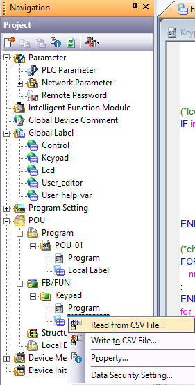
Now let’s try to connect the access control program we wrote earlier with display support. In addition to controlling the relay output for 3 seconds, we will greet our user and display their name and surname on the screen:
Result:
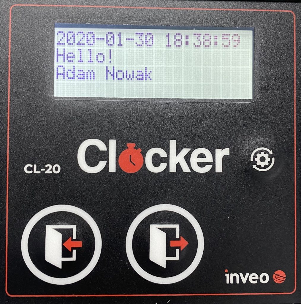
Finally, it can enrich our system with a sound signal in case of successful authorization by adding support for the state of the “Q_soundAccept” variable.
Keyboard
The last programmable element of the reader, depending on the version, can also be a keyboard, and it is time to operate it. In the case of readers with a keyboard, in addition to the blocks: “Control”, “User_editor” and “Lcd” we also have the “Keypad” block, but for convenient keyboard operation we will need the “Keypad” function block.
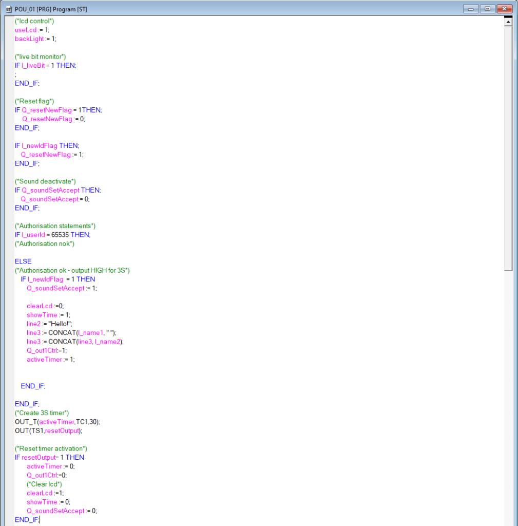
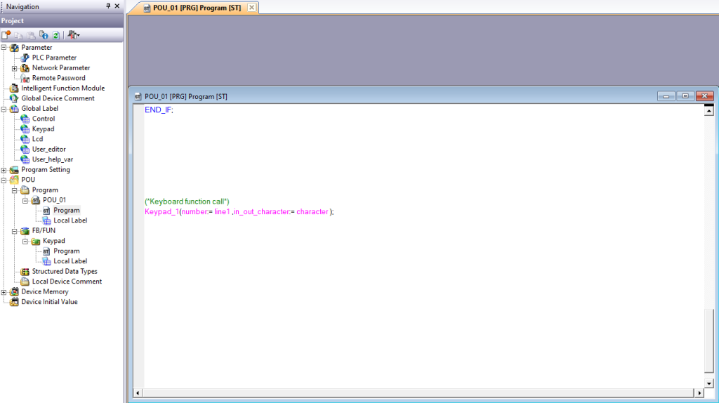
A new function block in the ST language should be added to the project and named “Keypad”

The variable block should be imported from the Local Label -> “Keypad.csv” file, and the function block source code should be copied from the Local Label -> “Keypad_script” text file.
After performing the above steps, you can call the function block in the main file by assigning the variables: “clearLcd”, “line1” and “character” to the appropriate places.
The “character” variable comes from the “Keypad” block, the “number” variable is the keyboard output string, in this case we assigned the first line of the LCD display as the place to display the content entered from the keyboard.
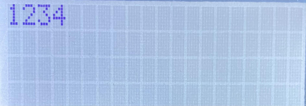
After calling the function and assigning the string to the first line of the display, we can enter any sequence of digits:
Conclusion
Thank you for taking the time to read our manual on integrating BoxID/Clocker readers with Mitsubishi PLCs! We hope that the information in the manual will help you implement this solution in your projects. If you have any questions, do not hesitate to contact our support team.
Good luck with your integration!